Category Archives: Tube

Another New Build

This unit was built for Mario Voltolini in Italy. It uses a new motherboard pcb and LCD display board designed by Eric Thacker and a number of new subassembly pcbs designed by yours truly. These new boards support the modifications devised by Steve Mitchell and myself to improve the sound and suitability of the Yuan Jing 6N3 valve preamp for use with a guitar input, rather than its original design purpose as a HiFi preamp.

There is also a neat little MIDI interface board and a switchable Cutting Edge Filter (CEF) as per the design by Charlie Hall.

Mario requested the ability to turn off the echo by using a remote footswitch so I added a bypass circuit using a signal relay to bypass the echo module. It’s not true bypass as we wanted to retain the tone of the valve preamp when bypassed.

Click on the thumbnails below for a larger picture and explanatory captions.

Test recordings


Valve Echotapper Recordings

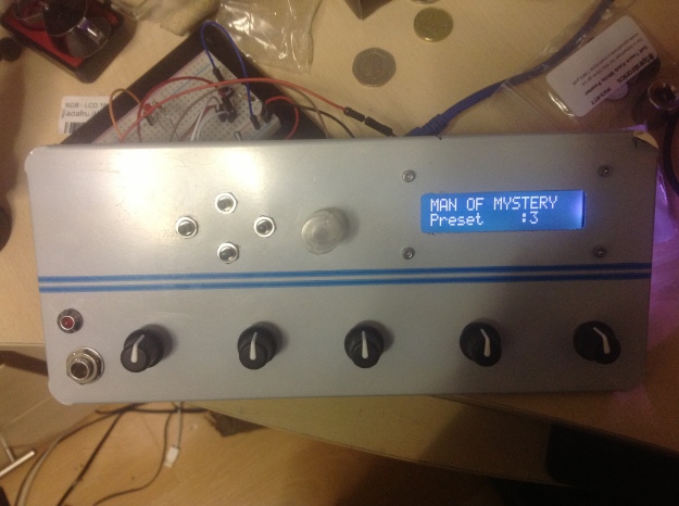
I’ve just completed what I’m calling ‘Stage 3’ of the modifications to the Yuan Jing 6N3 valve (tube) pre-amplifier that Steve Mitchell and I have been working on. As you probably know, Eric Thacker (aka Ecca) originally came up with the idea to use a fairly low-cost ready-made Chinese valve preamp that is available from various sellers on eBay, as a front end to the eTap2HW module programmed by Piet Verbruggen to emulate the vintage echo machines used by  Hank Marvin, the lead guitarist of the British group The Shadows.

Based on the ‘Matisse’ circuit, it’s design is intended as a HiFi preamp and as such the original sound was not ideal when it came to be used as a preamp ahead of the SKRM-eTap2 echo module. Working with a simulation of the circuit, Steve came up with a number of changes to make it more guitar and eTap2 friendly. I then tested these in the real world and gave feedback to Steve which enabled him to make further tweaks until we were happy with the result; though no doubt he’s busy thinking up a few more for me to try even as I’m typing these words 🙂

I will shortly be providing the details of how to carry out these modifications but in the meantime I feel the time is right to publish a couple of test recordings that I have made using the ‘Stage 3 Modified’ Valve Echotapper so others can judge the results for themselves.

In both these recordings (which are made for the sole purpose of education and research) I have used the original recordings by The Shadows but have been able to turn Hank’s lead guitar parts on and off as and when I wish. I recorded myself playing the lead part to this ‘backing track’ and rendered the finished tracks you will hear below and alternated the lead part between Hank and myself. (There is a short section just after the start of “Theme for Young Lovers” where we both play together).

No additional effects were added to Theme for Young Lovers. Blue Star had some EQ added to the recorded track before rendering it to the final mp3.

eTap2HW Poll Results

Thanks to everyone who took the time to listen to the samples from my three eTap2HW-based EchoTapper variants and cast a vote in my poll on which sound they preferred.

There was a very clear preference for Track ‘C’ which polled 55% of the votes, in second place was Track ‘B’ which polled 30% and coming well up the rear was Track ‘A’ with a mere 15%.

Now it’s time to reveal the details of the ‘competitors’…

  • Track ‘A’ was the unit with the valve preamp (15%)
  • Track ‘B’ was the unit with the unmodified FET preamp (30%)
  • Track ‘C’ was the unit with a modified FET preamp with optimized bias (55%)

Which really makes me wonder about all the fuss and hullabaloo on some of the Shadows forums regarding how ‘good’ the valve preamp-based units sound. My personal opinion is that the valve preamp sounds too ‘mellow’ with not enough bite to get the sound of the early Shadows recordings. It does sound nice but comes nowhere near ‘that sound’ but maybe with some modifications to the circuit it could get closer – we shall see.

Incidentally, I also prefer the sound of the modified FET preamp, it gives more gain and punch though Piet’s original FET design is also excellent and the results of individual units can vary depending on the wide manufacturing spread of the specs for individual FETs.

The original sound samples are still available here if you’d like to audition them (again).

A Look Inside the Finished Unit

I’ve just completed the wiring and testing of the MIDI functionality. In my previous automation Mark II box the MIDI hardware was mounted on a small veroboard and soldered directly onto the MIDI sockets. In this Mark III version I wired up the MIDI circuit on an Adafruit Protoshield pcb together with the circuitry for an I2C EEPROM which would allow more patches to be stored but is not yet supported by the software.

Image

This shows the ‘stack’ of Arduino-style Shields – saves a lot of extra wiring doing it this way.

Image

The MIDI sockets and the Audio Out socket on the back panel.

Image

This is the MIDI/EEPROM protoshield. I haven’t plugged in the EEPROM yet as there is no support for it in the software.

The only remaining job is to wire the foot-switch socket for up/down preset selection.

Image

It Works … Works … Works… Works ….

… after an initial period when I got lovely sound but no echoes! The only mode that gave the right sound was Tremolo with Reverb. After checking the voltages sent by the Arduino to the SKRM module on the Eccamatic board (the three control Pots P0, P1 and P2 and the Mode selector SW0, SW1 and SW2) and found them to be working as expected I was stumped for a while 😦

Anyway, to cut a long story short, I found I needed to join the signal from the input jack to both the Left and Right inputs on the Eccamatic/SKRM board (previously I only joined to the Left input). Once this was done – success, we had lovely echoes and a quick check showed all the emulations and presets were working as expected – happy days 😀

Some sound samples will follow as soon as I get a chance to record them.

Wiring – Stage 1

Connecting the EchoTapper Universal Interface shield (designed by Piet Verbruggen) to the Eccamatic Valve eTap2hw pcb (designed by Eric Thacker aka ‘ecca’).

The blue (Pot0), violet (Pot1) and grey (Pot 2) wires send the control voltages from the Arduino to the SKRM module (not yet mounted) on ecca’s board. The brown (+3.3V), red (SW0) , orange (SW1) and yellow (SW2) wires send the echo model select signals to the SKRM, replicating the action of the original BCD switch in the manual eTap2hw.

The rotary encoder, the push switches and the input jack socket are also wired on the front panel. The next stage is to wire up the front panel pots and the ‘peak’ LED.ImageImage

3D Model in SketchUp

I used Google Sketchup (a free 3D modelling package) to design the layout of the Valve Preamp EchoTapper. Here are a couple of views

Image

An isometric view of the complete 3D model

Image

Top half of the case ‘removed’ – you can put components of your model in different Layers in SketchUp and hide or show layers as you wish – a neat feature 🙂

Back panel removed

Back panel removed

Mounting the PCBs

I’ve now mounted the pcb’s for the valve pre-amp and the Eccamatic motherboard. I made a last-minute decision to mount the Eccamatic pcb in a vertical orientation after I suddenly realized it would fit that way. This frees up a bit of space for the connections between the boards and leaves a bit of room for future expansion – if I think of anything to do with it 😉

ImageImageImage

In the Box

This is the front panel fitted into the Conrad Electronics Steel/Aluminium enclosure 520470. I’m very impressed with the quality of this box. The top and bottom halves of the case are 1.5mm steel with black powder-coated finish and louvres. The front and rear panels are brushed aluminium 1.0mm thick with flanges on all four sides, making them pretty rigid.

Image